
Blog
Classification of Cutting Fluids
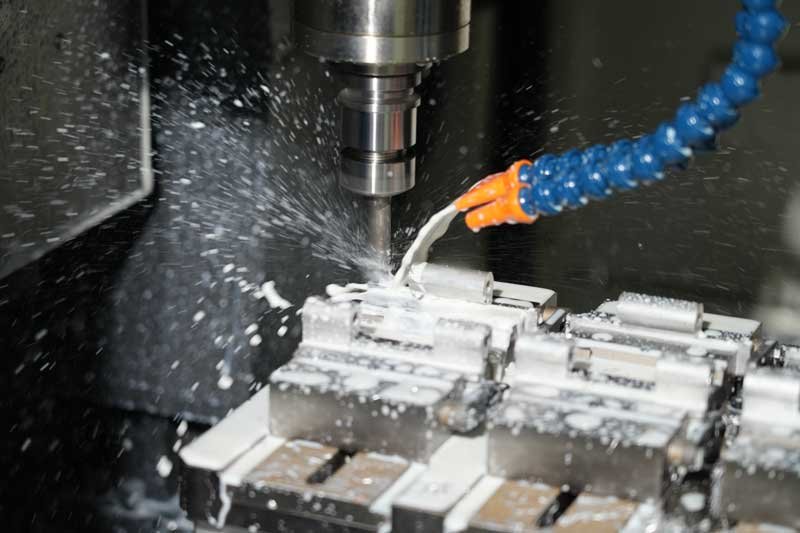
Cutting fluids are widely used in CNC lathe machining environments, continuously injecting vitality and efficiency into metal cutting operations through flexible application methods such as precise injection, fluid spraying, or fine mist.
How can a U-drill be machined on a CNC lathe?
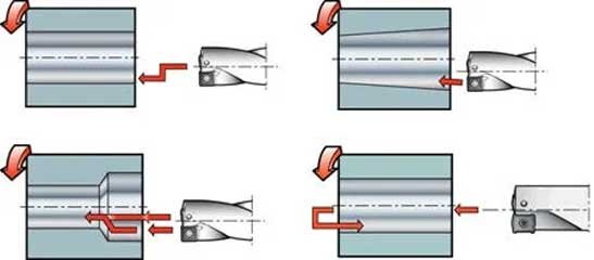
When using a U-drill for drilling on a CNC lathe, the maximum radial adjustment for drilling depends on the overlap between the U-drill’s central and peripheral inserts. Radial adjustment affects the cutting force, so it’s recommended to choose a lower feed rate within the suggested range.
Plane Definitions of G17, G18, and G19
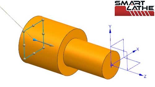
These three commands restrict tool movement to the specified plane, thereby preventing incorrect plane selection during machining, which could otherwise lead to tool collision or workpiece damage. Therefore, using the G17, G18, and G19 codes is essential for ensuring machining quality and safety.
Chip-Breaking Function of the Smartbrain CNC System
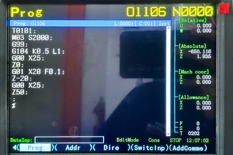
During the machining process, this function controls the flow and breaking of chips through system codes, creating an effective chip-breaking process.
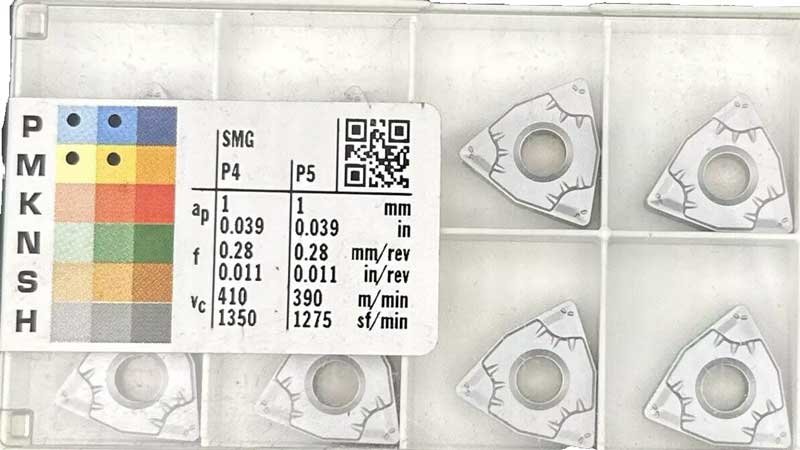
Principles for Selecting Cutting Tools
Any time a tool stops working, production halts. However, not all tools have the same level of importance. The tool that is used for the longest cutting duration has a greater impact on the production cycle, so its performance should be prioritized under equal conditions. Special attention should also be given to tools used for processing key components and those with the strictest tolerance requirements. Additionally, tools with poor chip control, such as drills, grooving tools, and threading tools, should be closely monitored because poor chip control can cause tool wear or machine downtime.
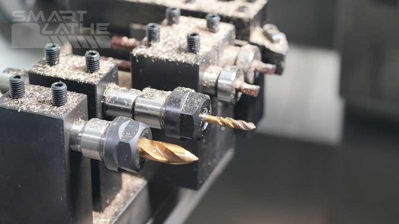
What is a tapping protector and what does it do?
The tool holder used will have an overload protection collet, functioning similarly to the tapping protector; it adjusts torque, increasing torque clockwise and decreasing it counterclockwise.
During processing, if torque increases, the tool holder will rotate freely, effectively protecting the tap and extending its lifespan. The torque will also vary to provide overload protection.
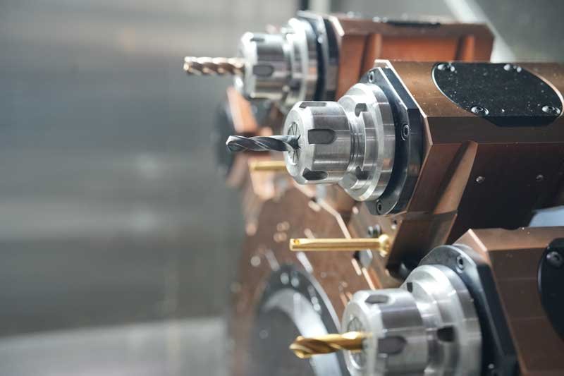
Installation Method of Cutting Tool ER Collet
The ER collet is a common clamping device used to hold tools or workpieces, widely applied in CNC machines, milling machines, and drilling machines. The installation sequence of the ER collet is critical to ensuring the reliability and precision of clamping.
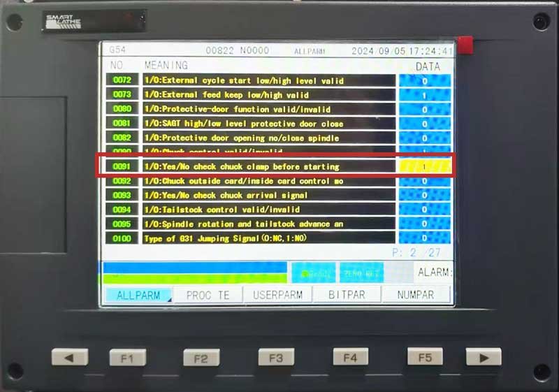
Smartlathe Brain System Chuck Clamping Mode Switch: Internal and External Clamping
In the daily CNC lathe production process, it is often necessary to change the chuck clamping method depending on the workpiece clamping needs. The smartlathe brain CNC lathe control system sets the parameters for switching between internal and external clamping. It is possible to quickly switch between the clamping methods by changing only one parameter setting.
Tolerance Compensation for Twin-Spindle CNC Lathe
Tolerance compensation is divided into thermal compensation and geometric compensation. The machine tool has a compensation system primarily composed of a microcomputer integrated with the machine tool controller.
The compensation value is calculated by the microcomputer based on the temperature signals from the machine tool and the worktable's motion position signals, combined with the comprehensive Tolerance mathematical model. The value is then sent to the machine tool controller to provide additional feed movement to the tool carriage for real-time compensation.
The main sources of thermal Tolerance in machine tools are the motor, bearings, transmission parts, hydraulic systems, and external and internal heat sources such as environmental temperature. These sources cause thermal deformation in the machine components. These Tolerances can be reduced by improving the machine structure during design and manufacturing. However, in most cases, machine Tolerances cannot be reduced by design and manufacturing techniques alone.
Differences Between BMT and VDI Turrets
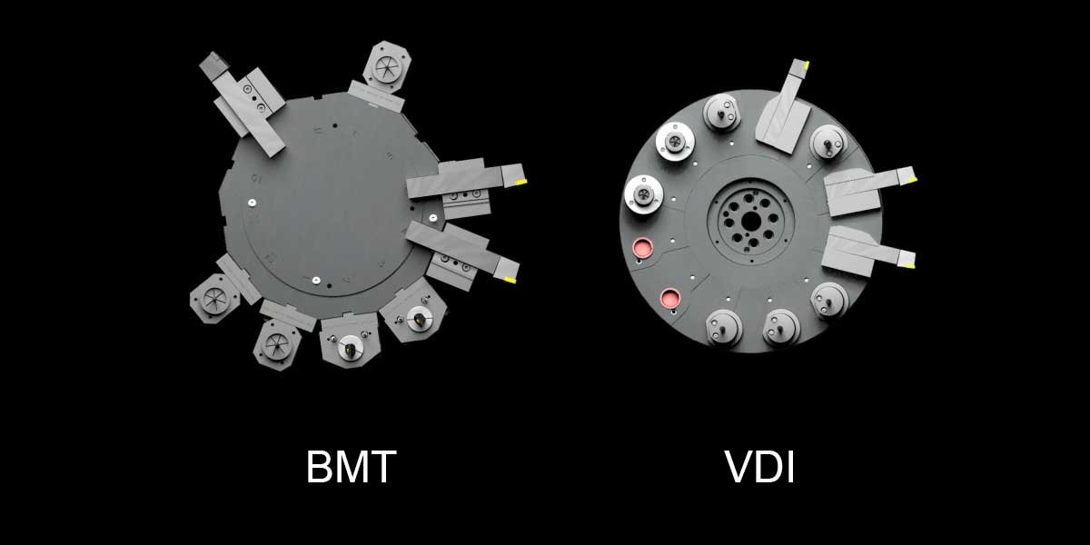
In the field of CNC machine tools, BMT (Base Mount Turret) and VDI (Verband Deutscher Ingenieure) are two common types of turrets. They differ in terms of process, structure, precision, and operation, each suited to different machining needs. This article will provide a detailed comparison of these two turret types.
Classification of Gear Machining on CNC Lathes
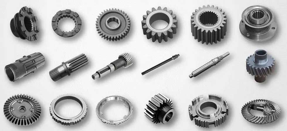
Gear machining on CNC lathes is a crucial aspect of gear manufacturing, involving various machining methods and tools. Based on the machining method and the type of gear, CNC lathe gear machining can be primarily classified into: forming machining, gear hobbing, gear shaving, etc.
End Face Grooving
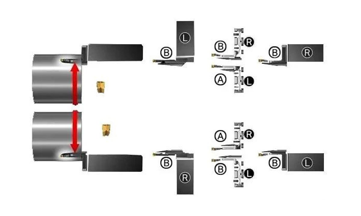
On CNC lathe, when machining end face grooves on the surface of a part, selecting the correct tool is crucial. The radius of the groove will determine the curvature of the tool. Since the groove is arc-shaped, chip removal can become an issue. Chips clogging the groove can lead to blade breakage, creating safety hazards.
Vibration Damping Principle of Cast Iron
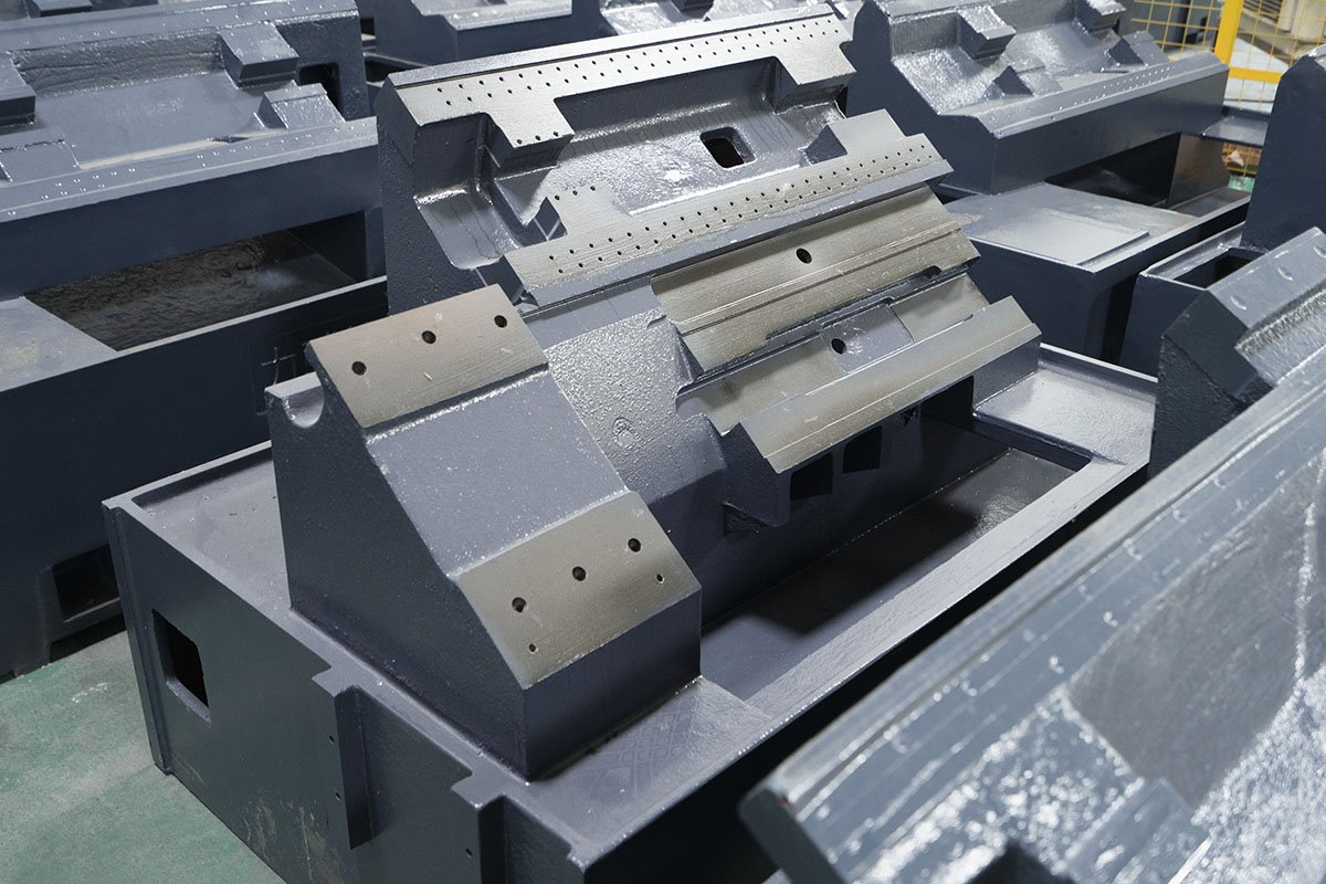
The material selection for the base of a CNC lathe is critical for ensuring the stability and precision of the machine. Commonly used materials for the base include cast iron, steel, and concrete. The base provides high rigidity and stability, absorbing vibrations during machining to ensure processing accuracy. The design of the base ensures the overall stability of the machine, reducing thermal and mechanical deformation, thus enhancing the machine's lifespan and machining quality.
Considering that CNC lathes prioritize stability and require strong vibration damping, cast iron is typically chosen for the base over steel. This is often achieved through integral molding, reducing the need for welding and assembly processes, lowering manufacturing costs, and improving production efficiency.
Calculation of Machining Time for Facing, Parting Off, and Deep Grooving on a CNC Lathe
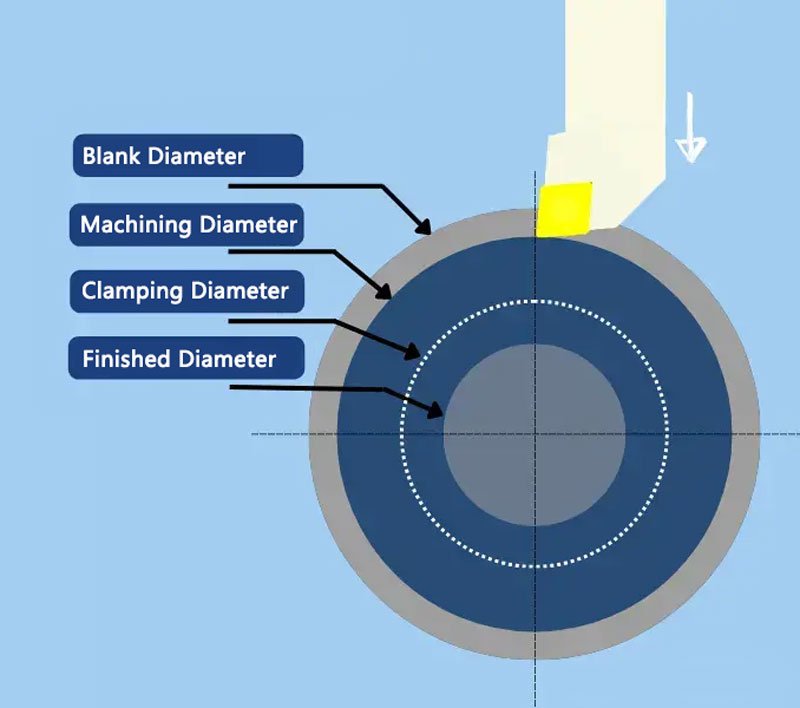
SMARTLATHE often needs to calculate machining times during the analysis of CNC lathe drawings. While CNC programming software can typically complete these calculations quickly, it is important for us to understand how the software performs these calculations.
Comparison of Helical Splines and Straight Splines
1.1 Helical Splines
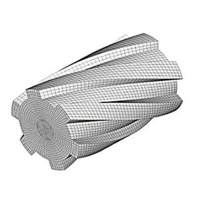
The spline teeth are helical, similar to threads. The tooth surface is at a helical angle, with a smaller tooth profile angle. The design is more complex, and the manufacturing difficulty is higher.
1.2 Straight Splines
The spline teeth are straight, parallel to the spline axis. The tooth surface is parallel to the axis, with a simple tooth profile. The design is relatively simple, and manufacturing is easier.
Classification of geometric tolerances during CNC lathe machining—Guide rails
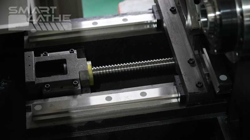
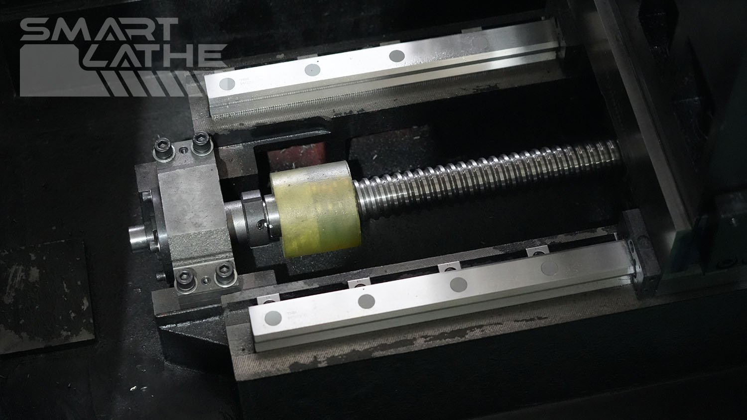
The geometric tolerances of CNC lathe guide rails have a significant impact on machining accuracy and workpiece quality. These tolerances mainly include horizontal straightness tolerance, vertical straightness tolerance, and parallelism tolerance of the guide rails.
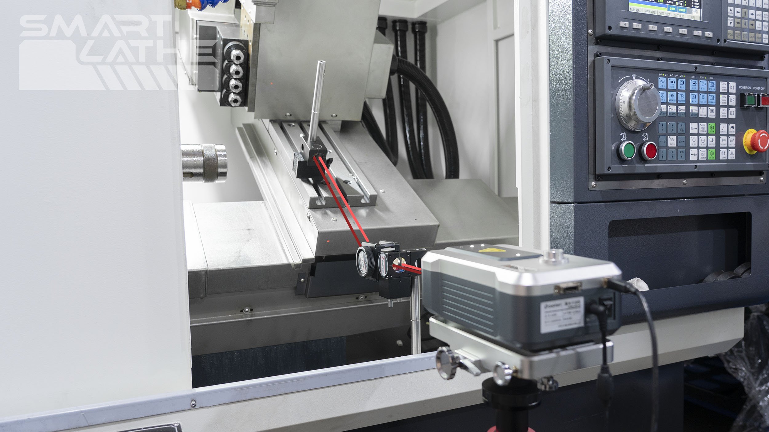
The Difference Between Positioning Accuracy and Repeatability in CNC Lathes
In CNC lathe operations, positioning accuracy and repeatability are two key parameters that directly affect machining quality and production efficiency. Understanding and correctly applying these concepts can help optimize the machining process and improve product quality. This article will detail these two concepts and their differences.

Selection of Threading Inserts for CNC Lathes
When performing threading on a CNC lathe, it is crucial to select the most suitable threading inserts for your application based on the insert type, flank/radial clearance, and insert profile. These factors significantly impact chip control, insert wear, tool life, and thread quality.

Adiabatic Shearing Phenomenon in High-Speed Cutting
In the field of precision manufacturing, high-speed cutting technology is highly regarded for its efficiency and precision. However, behind this technology lies a complex physical process known as the "adiabatic shearing phenomenon." So, what is the adiabatic shearing phenomenon in high-speed cutting? Today, let's unveil the mystery behind this technology.
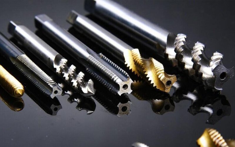
Common issues and solutions for rigid tapping
During the tapping process, various issues can arise that affect production techniques and efficiency. Today, we will analyze the solutions to common tapping problems.