Lathe Spindle Nose Identification Chart
To establish the type of spindle nose you have, look through the diagrams below. Make the necessary measurements after analyzing the related chart. For your chuck or adapter plate, choose the spindle nose size.
Sort D: Camlock
The body of camlock pins has a D-shaped cutout. They are utilized to attach a chuck to the spindle of a lathe.
There are three camlock pins on D1-3 to D1-4 chucks and adapter plates.
The adapter plates and D1-5 to D1-15 chucks contain six camlock pins.
A lathe operator mounts a chuck by inserting the camlock pins into the spindle of the lathe, pulling the camlock pins inward to tighten the chuck snugly against the spindle with a wrench to rotate a cam inside the spindle.

|
Spindle Nose Size |
A |
B |
C |
D |
E |
F |
|
D1-3 |
92 |
53.983 |
11 |
32 |
3x15.1 |
70.6 |
|
D1-4 |
117 |
63.521 |
11 |
34 |
3x16.7 |
82.6 |
|
D1-5 |
146 |
82.573 |
13 |
38 |
6x19.8 |
104.8 |
|
D1-6 |
181 |
106.385 |
14 |
45 |
6x23 |
133.4 |
|
D1-8 |
225 |
139.731 |
16 |
50 |
6x26.2 |
171.4 |
|
D1-11 |
298 |
196.883 |
18 |
60 |
6x31 |
235 |
|
D1-15 |
403 |
285.791 |
19 |
70 |
6x35.7 |
330.2 |
|
D1-20 |
546 |
412.795 |
21 |
82 |
6x42.1 |
463.6 |
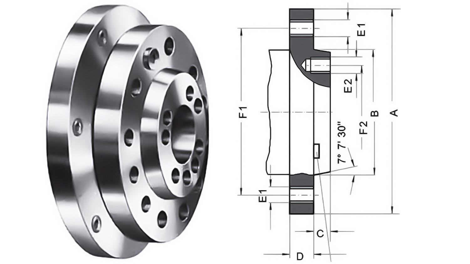
Type A1 - Short Taper
Tapped holes on outer-bolt circle and tapped holes on inner-bolt circle.
|
Spindle Nose Size |
A |
B |
C |
D |
E1 |
F1 |
E2 |
F2 |
|
A1-5 |
133.4 |
82.575 |
14.288 |
22.2 |
11x7/16-14 UNC |
104.8 |
8x7/16-14 UNC |
61.9 |
|
A1-6 |
165.1 |
106.390 |
15.875 |
25.4 |
11x1/2-13 UNC |
133.4 |
8x1/2-13 UNC |
82.6 |
|
A1-8 |
209.5 |
139.735 |
17.462 |
28.6 |
11x5/8-11 UNC |
171.4 |
8x5/8-11 UNC |
111.1 |
|
A1-11 |
279.4 |
196.885 |
19.05 |
34.9 |
11x3/4-10 UNC |
235 |
8x3/4-10 UNC |
165.1 |
|
A1-15 |
381 |
285.8 |
20.638 |
41.3 |
12x7/8-9 UNC |
330.2 |
11x7/8-9 UNC |
247.6 |
|
A1-20 |
520 |
412.8 |
22.225 |
47.6 |
12x1-8 UNC |
463.6 |
11x1-8 UNC |
368.3 |
Type A2 - Short Taper
Tapped holes on outer-bolt circle, no holes on inner-bolt circle.

|
Spindle Nose Size |
A |
B |
C |
D |
E1 |
F1 |
|
A2-3 |
92.1 |
53.985 |
11.1 |
15.9 |
3x7/16-14 UNC |
70.66 |
|
A2-4 |
108 |
63.525 |
11.1 |
19 |
11x7/16-14 UNC |
82.55 |
|
A2-5 |
133.4 |
82.575 |
12.7 |
22.2 |
11x7/16-14 UNC |
104.8 |
|
A2-6 |
165.1 |
106.390 |
14.3 |
25.4 |
11x1/2-13 UNC |
133.4 |
|
A2-8 |
209.5 |
139.735 |
15.9 |
28.6 |
11x5/8-11 UNC |
171.4 |
|
A2-11 |
279.4 |
196.885 |
17.5 |
34.9 |
11x3/4-10 UNC |
235 |
|
A2-15 |
381 |
285.8 |
19 |
41.3 |
12x7/8-9 UNC |
330.2 |
|
A2-20 |
520 |
412.8 |
20.6 |
47.6 |
12x1-8 UNC |
463.6 |
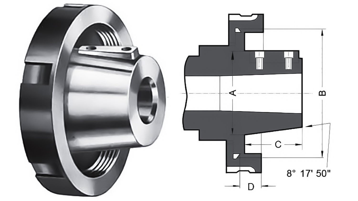
Type L - Long Taper
For centering and locating fittings, a key for positive location, and a flanged retention nut.
|
Spindle Nose Size |
A |
B |
C |
D |
Drive Key |
|
L00 |
69.850 |
3 3/4-6 UNS |
50.800 |
14.288 |
9.525x38.1 |
|
L0 |
82.550 |
4 1-2/-6 |
60.325 |
15.875 |
9.525x44.45 |
|
L1 |
104.775 |
6-6 UNS |
73.025 |
19.050 |
15.875x60.32 |
|
L2 |
133.350 |
7 3/4-5 UNS |
85.725 |
25.400 |
19.05x73.02 |
|
L3 |
165.100 |
10 3/8-4 UNS |
94.425 |
28.575 |
25.4x82.55 |
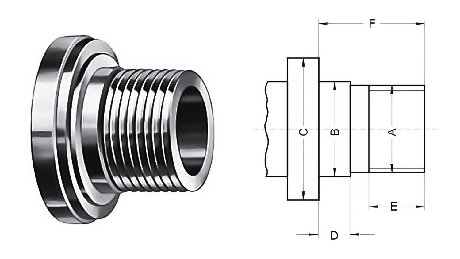
Threaded Plates
|
A |
B |
C |
D |
E |
F |
|
M 20 |
21 |
30 |
6.3 |
10 |
20 |
|
M 24 |
25 |
36 |
8 |
12 |
24 |
|
M 33 |
34 |
50 |
9 |
14 |
30 |
|
M 39 |
40 |
56 |
10 |
16 |
35 |
|
M 45 |
46 |
67 |
11 |
18 |
40 |
|
M 52 |
55 |
80 |
12 |
20 |
45 |
|
M 60 |
62 |
90 |
14 |
22 |
50 |
|
M 76x6 |
78 |
112 |
16 |
30 |
63 |
|
M 105x6 |
106 |
150 |
20 |
40 |
80 |