CNC machine programming origin and programming coordinate system
What is the programming zero point and coordinate system in CNC lathe machining programming?
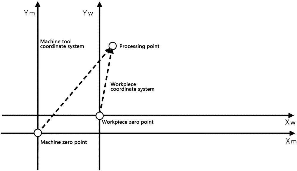
CNC machine tools have CNC device, machine operators, process programmers three different application objects, thus resulting in three coordinate systems: machine tool coordinate system (for the bottom of the CNC device coordinate system), the workpiece coordinate system (for the middle of the machine operator coordinate system), lathe programming coordinate system (for the upper level of the process programmer coordinate system). Correct selection and determination of the three coordinate systems, understanding the relationship between the three is very necessary for CNC machining and CNC programming.
What is programming zero point ?
The coordinate system's zero point, or the program zero point, is the programming zero point for CNC lathes. The programming zero point is often the workpiece zero point for simple parts. In other words, the workpiece coordinate system is the coordinate system used for programming. As a result, the size in the coordinate system of the workpiece determines the programming size. Several programs or subroutines are needed for parts with very complex forms. The programming zero point is not always at the workpiece zero point, but rather at a location convenient for programming in order to simplify programming and reduce the calculation of many coordinate values.
What is the CNC lathe's coordinate system?
Machine tool coordinate system
The machine tool's built-in coordinate system is used to calculate the coordinates of the machined parts inside the tool, as well as the particular positions of its moving components (such as tool change points and reference points) and its range of motion (such as the range of travel, protected areas). The ISO unified standard right-hand Cartesian coordinate system is used by CNC machine tools. The nomenclature of the machine axes is depicted below; three axes are parallel to one another, and the three fingers of each axes point in the positive directions of the X-axis, Y-axis, and Z-axis. Additionally, when a machine tool moves in more than three X, Y, and Z coordinates, it should employ the coordinates U, V, and W, which are parallel to the X, Y, and Z axes of the second group of linear motion, and P, Q, and R for the third group of linear motion, respectively. The positive direction of rotation with the right-hand spiral rule, the second group of rotary motion, can be called D, E, with A, B, and C, respectively, around the X, Y, and Z axes of rotary motion.
The origin of the machine coordinate system is called the machine zero point. The machine zero point is a fixed point on the machine tool and is determined by the machine tool manufacturer. It is the reference point for all other coordinate systems, such as the workpiece coordinate system, the programming coordinate system, and the machine reference point.
The two-dimensional coordinate system for the machine tool's X and Z axes is established from the zero point of the CNC lathe, which is typically in the center of the spindle's front face.
The reference point of the CNC machine tool is used for the machine table (or slide) and the incremental measurement system of the relative motion of the tool to calibrate and control the point. The stopper and limit switches on each axis of motion precisely predetermine the location of the reference point. As a result, the reference point's coordinates relative to the machine's zero point are a known fixed value.
Workpiece coordinate system
Workpiece coordinate system is used to determine the geometric elements of the workpiece geometry (points, lines, arcs, etc.) and the location of the coordinate system, the origin of the workpiece coordinate system is the workpiece zero point. The principle of choosing the workpiece zero point is to facilitate the conversion of the dimensions of the workpiece drawing into the programmed coordinate values and to improve the machining accuracy.
Turning workpiece zero point is generally placed on the right end face or left end face of the workpiece, and overlap with the spindle centerline. Milling workpiece zero point is generally located on the corner of the base of the outer contour of the workpiece, and the workpiece zero point in the direction of the feed depth is mostly taken on the surface of the workpiece.
Lathe programming coordinate system
The programming coordinate system is a coordinate system with the programming origin as the origin of the coordinate system for programming process personnel to program. Programming coordinate system of X, y, Z axis and machine tool coordinate system of X, y, Z axis should be parallel, positive direction consistent. After establishing the programming coordinate system, the programmer only needs to program according to the part drawing, lathe size requirements, axis direction and machining process and other factors can be easily programmed.

The CNC device can control the tool along the contour trajectory movement if the workpiece coordinate system is established, the machine tool coordinate system position is determined, and the processing of the CNC machine tools automatically points in the programming coordinate system in the center of the seat of the machining value into the point in the machine tool coordinate system coordinate value.

As a result, the workpiece coordinate system serves as a link between the machine tool coordinate system and the programming coordinate system. The machining center coordinate system and the programming coordinate system are established through the use of the workpiece coordinate system. Any point's coordinates with respect to the machine tool's programmed origin can be automatically converted by the CNC device to coordinates with respect to that origin.